TFE731-5BR 11/22/19
There is another 1000 lbs of thrust available with the TFE731-5BR but likely
intake issues that would drive the need to de-rate the output. The idea of
flat rated thrust irrespective of ambient temperatures or altitude for that
matter is mighty attractive. Hot sections are on condition for my
maintenance plan so a hot section that ran, say, 100 degC cooler would last a
very long time. There would be a weight penalty (something like 75 lbs - I
need to check) which would require more nose ballast. Still, a hundred
more pounds for hundreds more in thrust is mighty attractive.
Ed is busy generating inlet geometry from the L-139 drawings and exit
geometry from our fan duct and exit tube design. Computational fluid
dynamics (CFD) is next to get a feel
for where problems will arise then its time to instrument up an installation
with pressure sensors. It has been my experience that CFD without real
world correlation is helpful but far from definitive.
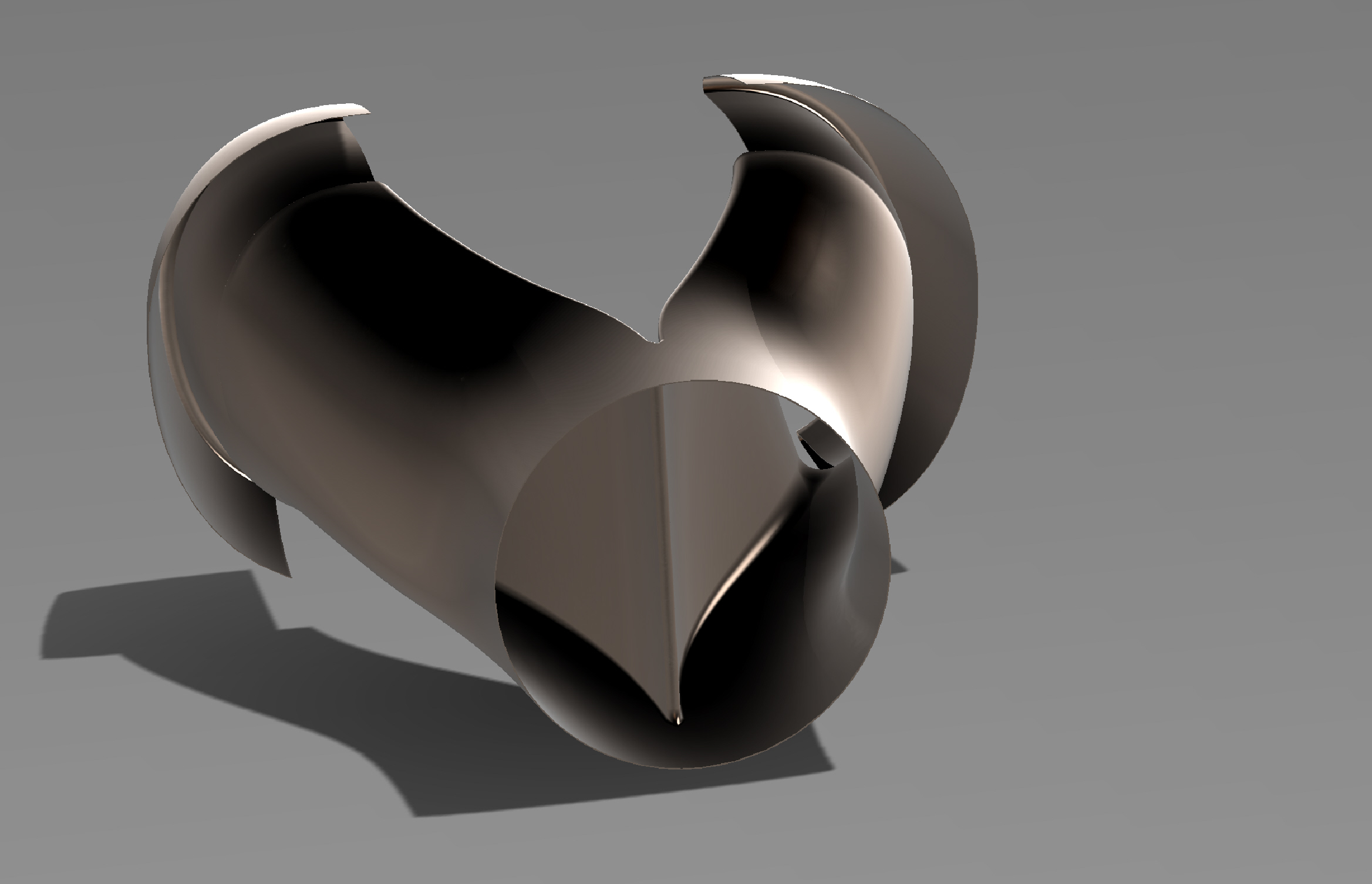
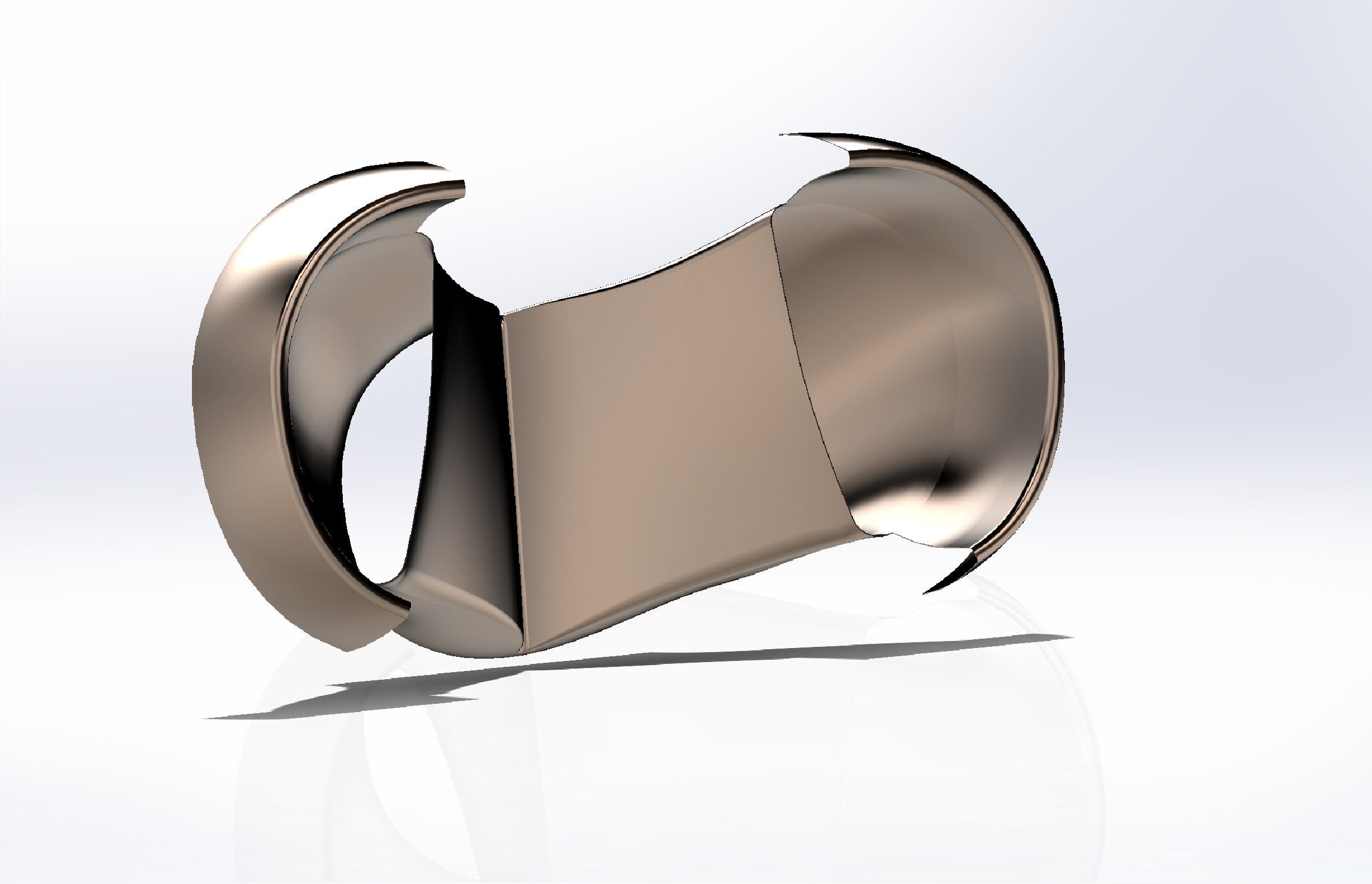
The whole air tract changes with a -5BR installation.
This rendering gives an indication
of what is needed. Once again, composites provide a distinct advantage in
shaping ducts that do not disrupt airflow.
The L39MS uses the DV2 motor (shown below) with around 1000 lbs more thrust.
This would seem to indicate that a -5 with similar thrust could be made to work.
The CFD modeling and analysis has begun. There are a couple of pics
of the initial models but these are VERY early days in the process and the model
requires a lot more work before simulation runs are possible. As mentioned
above, CFD results are nice but to be truly useful they must be correlated to
real world pressure data and the models adjusted accordingly. I'm working
on both a -3 and -5 inlet with integral pressure sensors around the fan
periphery to collect just such data. We are at the start of a very long
road.
Now that Grey is fully into Phase 1 test flights with a dedicated test pilot
(as of mid 12/18), my focus has turned to a couple of sets of -3 conversion
parts and full on the -5 installation in UDuck..... I'm not sure what we
will end up with but we are going to try.
Well, I did not see that coming. We lost access to Grey to do customer
demos so UDuck is becoming Mallard but is being built with a -3 instead of a -5.
We have purchased "Mojave" and, as of today (6/11/19), it is being collected in
Mojave to be shipped to Florida. This will now be our -5 project.
You can knock us down but we will get right back up and re-double our efforts.
We are well down the path of completing Mallard as our in house -3 demo plane
and are, once again, working on the -5 conversion. We need to get it done
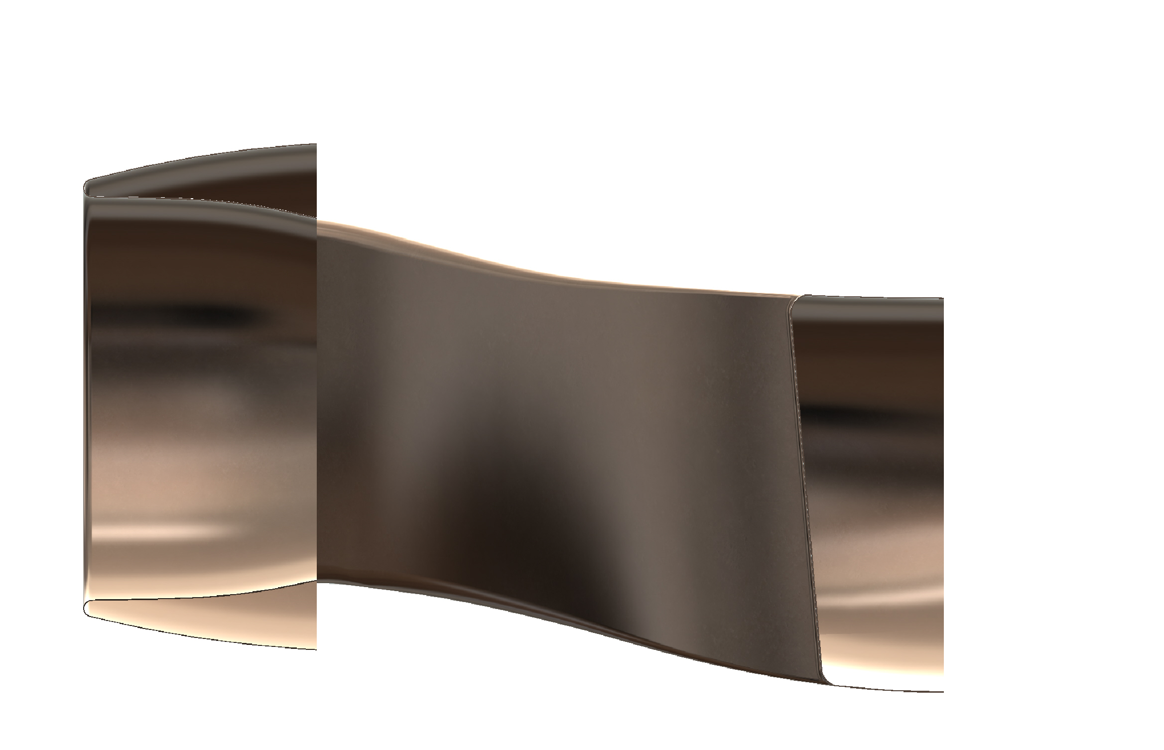
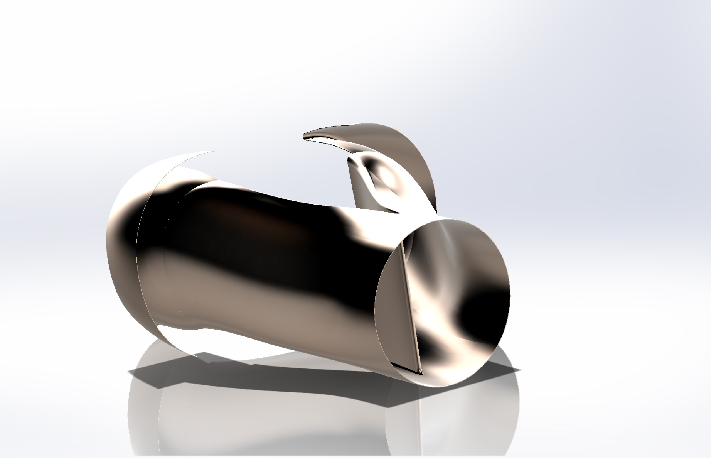
in time for Reno next year :) Below is a rendering from our gas flow path
work looking mostly at the differences between the -3 and -5 post fan gas path.
Here is a more complete look at the
model.
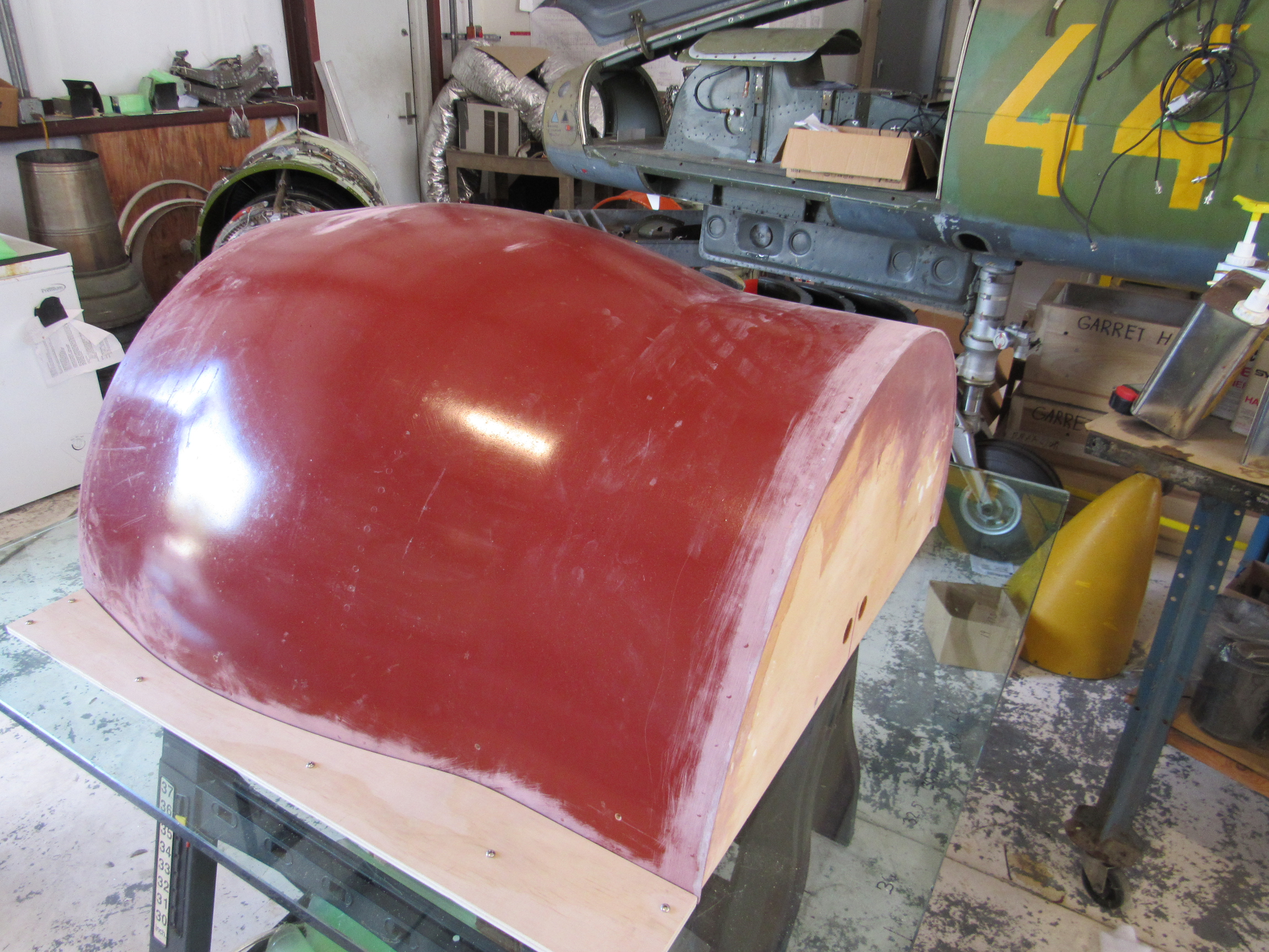
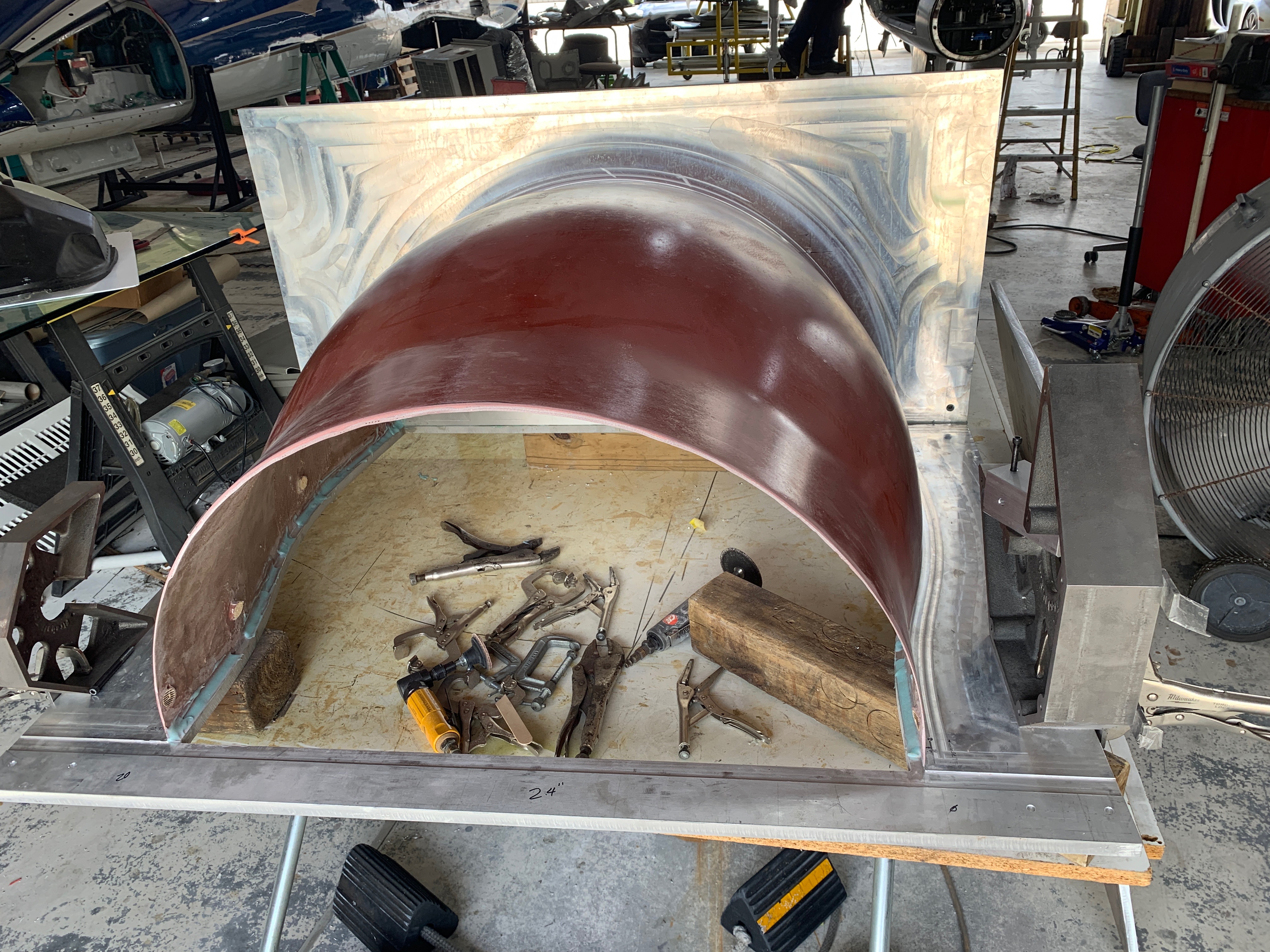
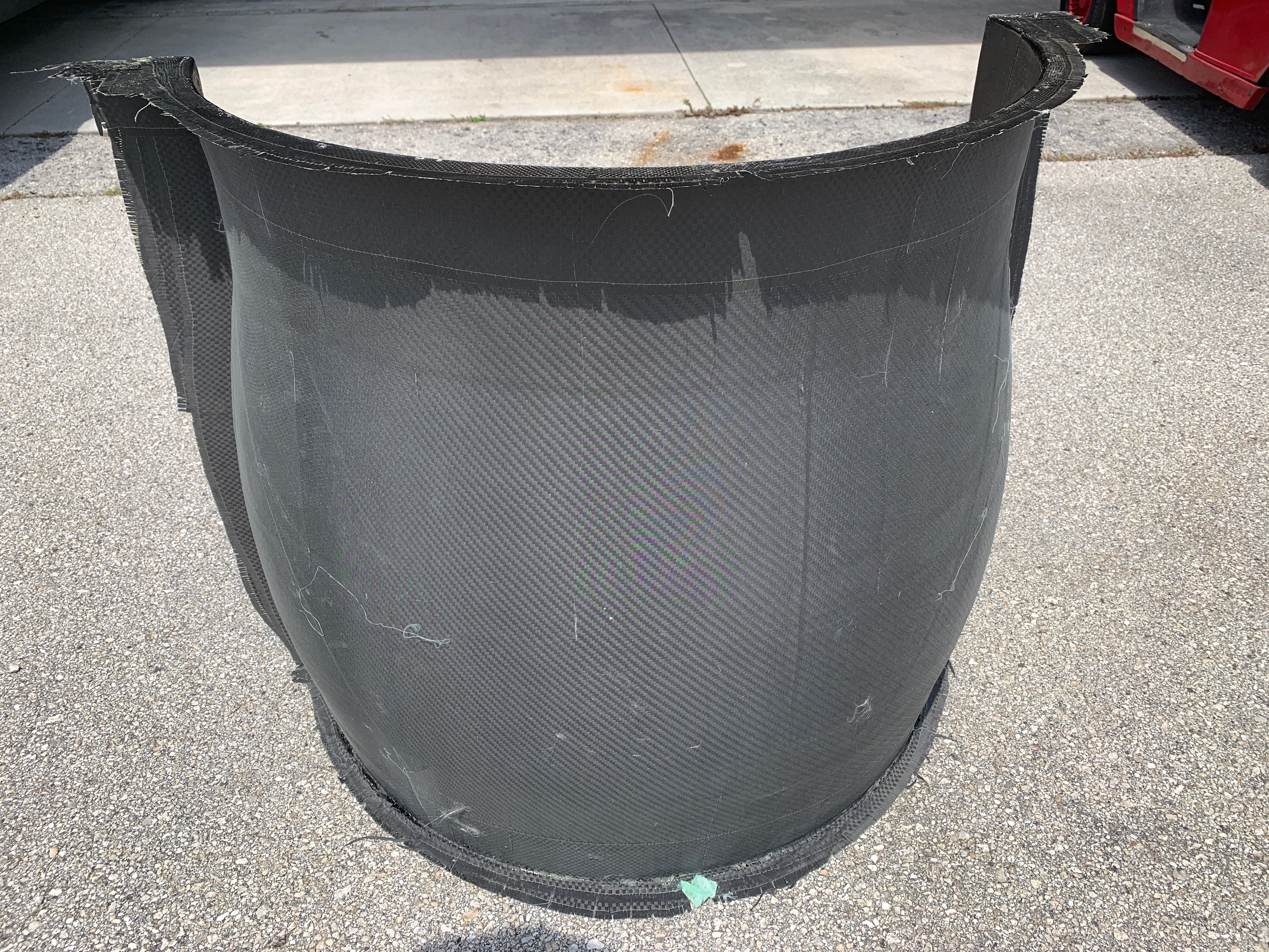
The first fan exit duct part is off the mold and has been oven cured.
It is test fit to the motor and we will soon be rolling it into the fuselage to
start working on everything from the exit tube to bleed air plumbing. It
looks like the exit tube may need to be a monolithic carbon structure. We
will need to get some -5BR exhaust temperature readings before making that
decision.
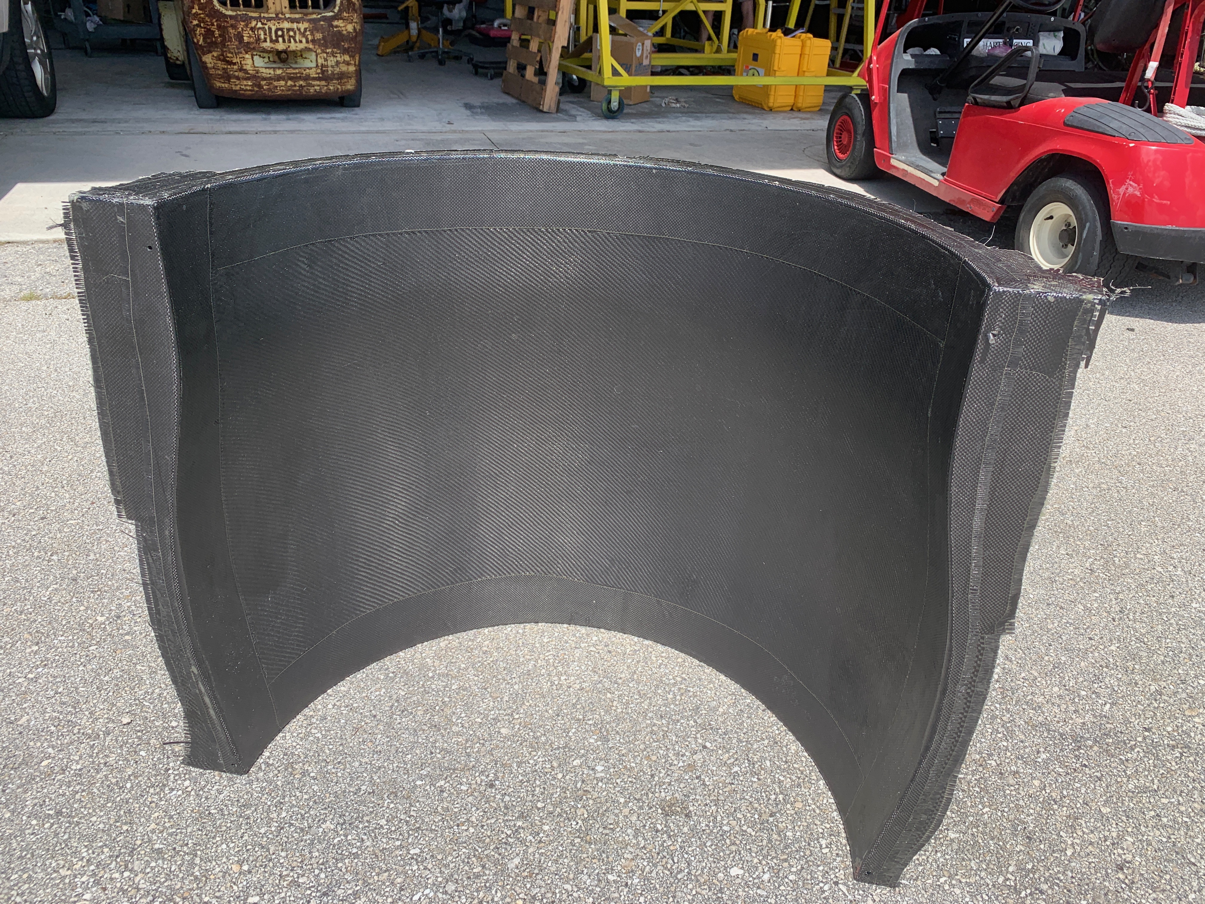
Many thanks to Paul and his patience in working with us on improving our
composite technique. The -5 duct part is the first to use his improved
breather technique and results were fantastic. Very good resin control and
vastly superior material compaction. Our previous parts were good and
these are better. There is more improvement to come as we incorporate more
of Paul's teachings.
Its a work in process.
|
|
|
|

|
|
|
|
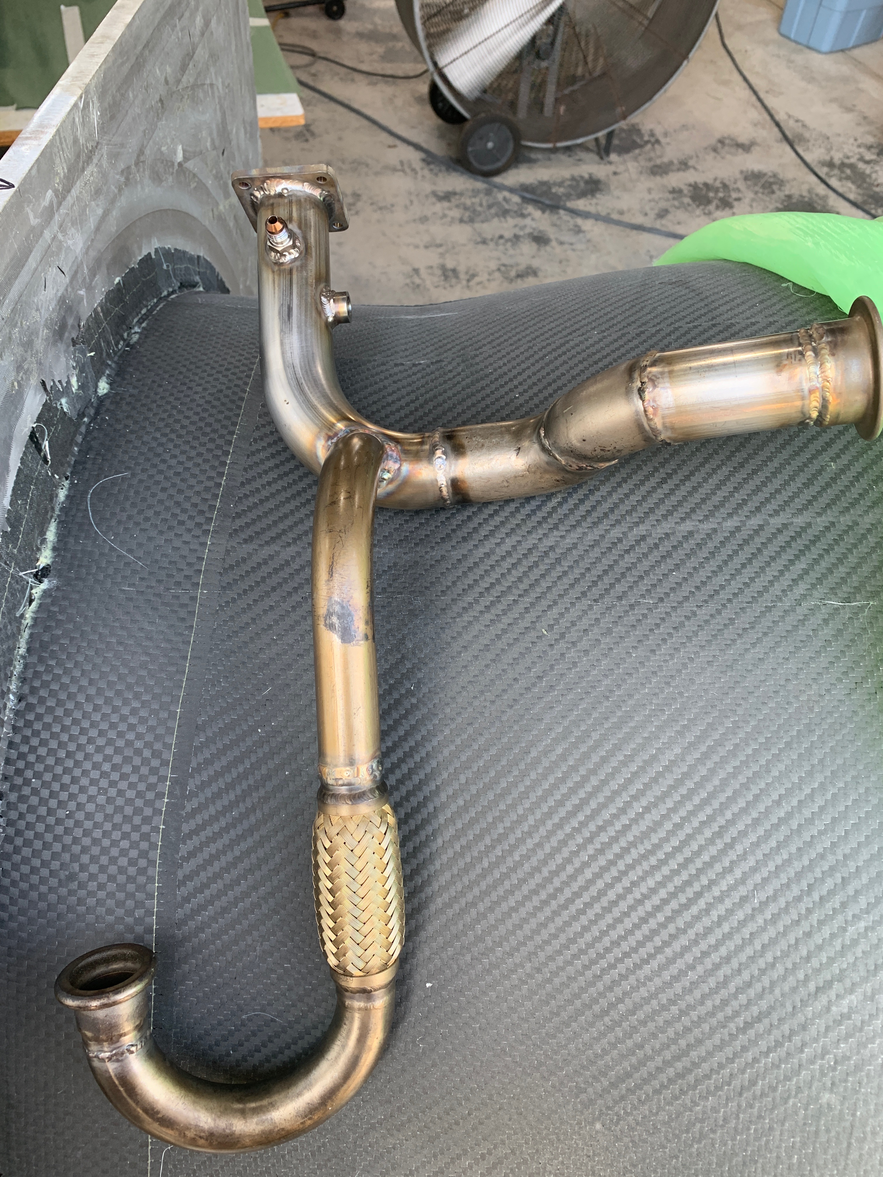
-5BR powered pickup - a fast way to get your motors home |
|
|
|
|
|
|
|
|

|
|
|
|
Hans with his current work of art |
|
|
|
|
|
|
|
|
|

|
|
|
|
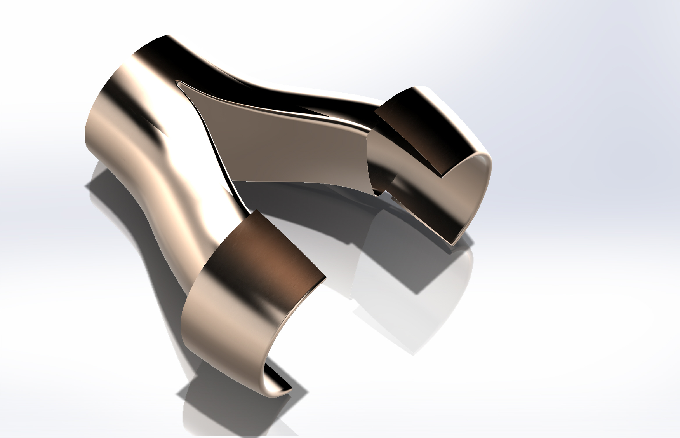
The Falcone exit Nacelle is a work of art. Pulling a skin to act as a mold was straight forward. |
|
|
|
|
|
|
|
|
|
|
|
|
|

|
|
|
|
The DV2 appears to be a higher bypass fan motor |
|
|
|
|
|
|
|
|
|
|

|
|
|
|
Very early days in the CFD work |
|
|
|
|
|
|
|
|

|
|
|
|
Just starting to get the models sorted |
|
|
|
|
|
|
|
|
|

|
|
|
|
Ed got a little curious about overall airframe effects - next thing we know, the airframe is modeled |
|
|
|
|
|
|
|
|

|
|
|
|
It is interesting to see how the inlets pull air from the surroundings |
|
|
|
|
|
|
|
|
|

|
|
|
|
and how air comes off the nose |
|
|
|
|
|
|
|
|

|
|
|
|
Some renderings from the Parametric Model |
|
|
|
|
|
|
|
|
|
|
|
|
|
|
|
|

|
|
|
|
-3 -5 Gas Path Differences |
|
|
|
|
|
|
|
|
|

|
|
|
|
Here are some pictures of the -5 Fan Exit Duct Mold Build |
|
|
|
|
|
|
|
|
|
|

|
|
|
|
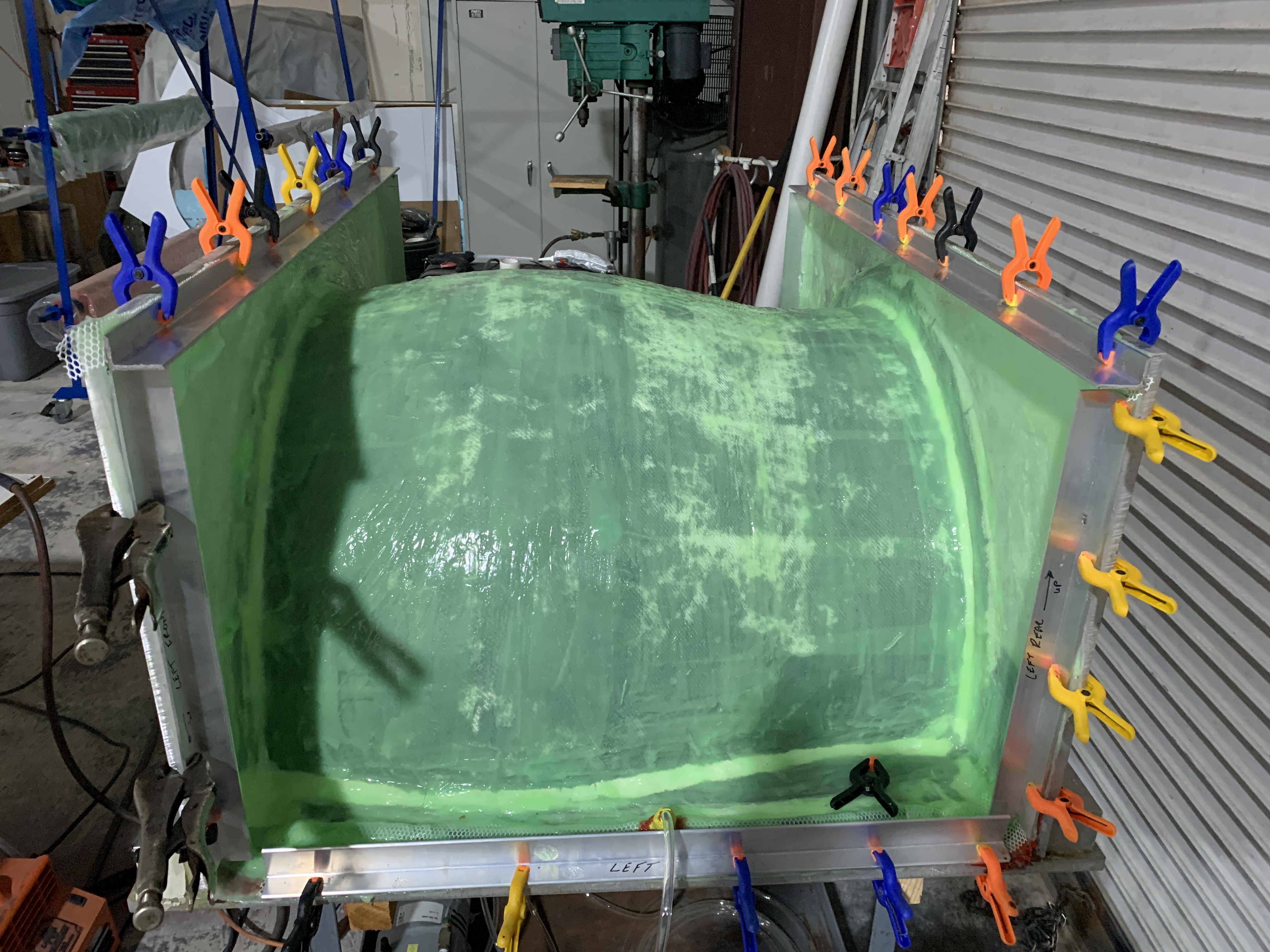
Sealing is important for Vacuum Integrity |
|
|
|
|
|
|
|
|

|
|
|
|
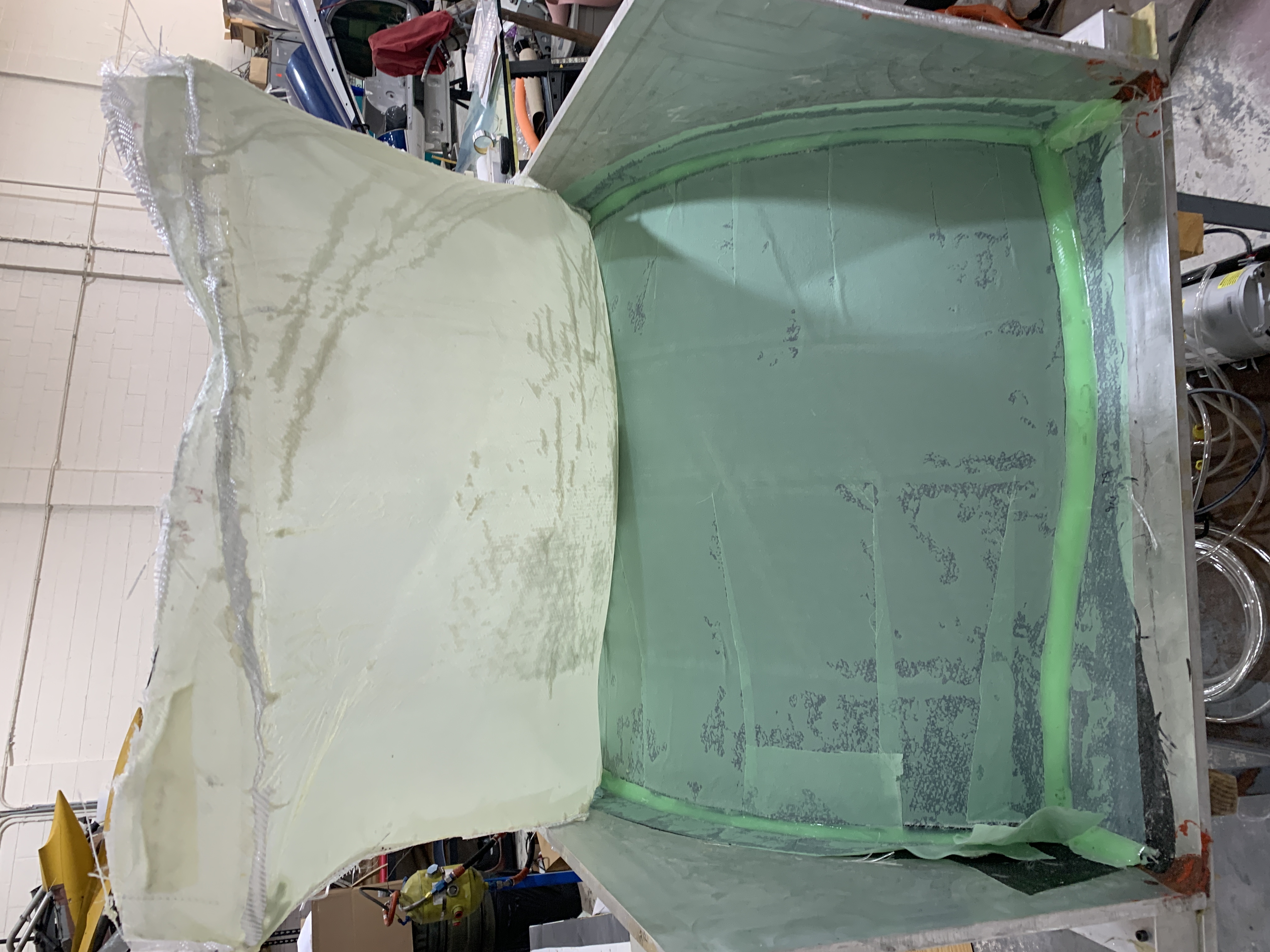
End plates must be true if the flanges are to fit the motor and seal |
|
|
|
|
|
|
|
|
|

|
|
|
|
Bagging the part with the new breather technique |
|
|
|
|
|
|
|
|

|
|
|
|
First part coming off the mold |
|
|
|
|
|
|
|
|
|
|
|
|
|
|
|
|

|
|
|
|
Latest part and process using satin weave full layer sheets |
|
|
|
|
|
|
|
|
|
|
|