UltimateL39 Bleed Air System
Email Questions or
Comments
The UltimateL39 bleed air system is a combination of design concepts from the
L139, components from the AI-25 and bespoke elements to simplify the system and
provide for a high quality, low production run repeatable solution for our
customers.
Overall, the bleed air system starts by mixing High Pressure (HP) and Low
Pressure (LP) bleed air from the TFE731 motor in such a way as to not exceed the
energy in the bleed air provided by the original AI-25. This is
accomplished on the TFE731 engine using a bespoke HP pressure dependent shut off
valve connected to a LP port mounted mixing manifold. The mixing
manifold as a commercially available one way "flapper" valve to prevent HP air
from entering the LP port on the motor when the airframe systems are consuming
HP air. This approach is similar to that employed on the L139. It
allows for good air conditioner performance at idle using HP bleed air then a
transition to LP bleed air slightly above idle. Bleed air energy is
controlled and the minimum parasitic loss is applied to the motor saving that
energy (thrust) for the pilot.
The L39 uses several flow limiting valves that are matched to the
energy in the one (and only) bleed air source (final compressor stage) of the
AI-25. If you use the existing flow limiter/regulators but dramatically
exceed the bleed air energy of the AI-25, bad things can happen like blowing up
the Air Cycle Machine (ACM) or Turbo Cooler as it is known in the L39.
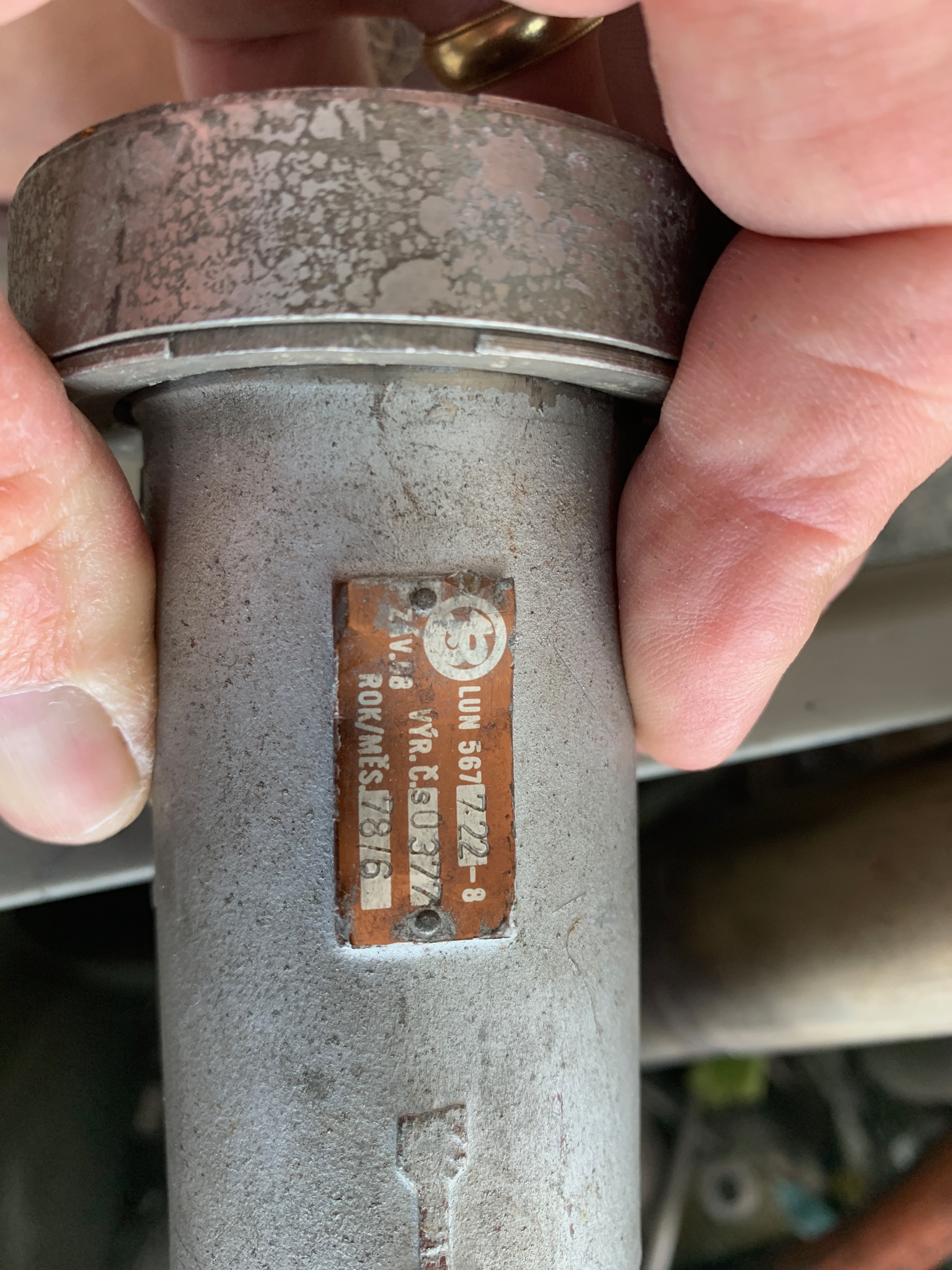
Ask me how I know :) The mixed air
described above is piped via 1 1/2" thin wall stainless tubing covered in
fiberglass heat wrap (header wrap) and high temperature shielding tape to one of
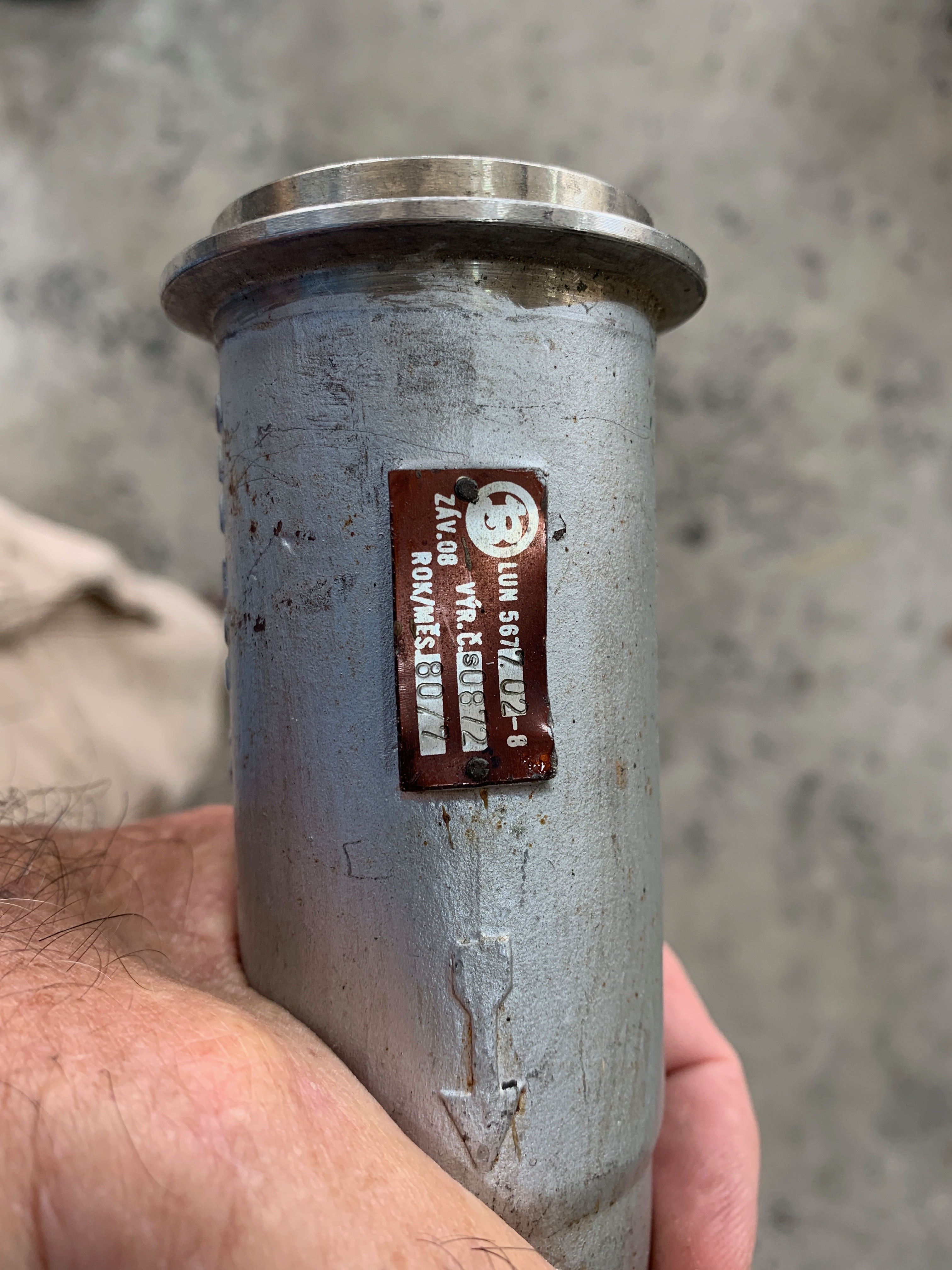
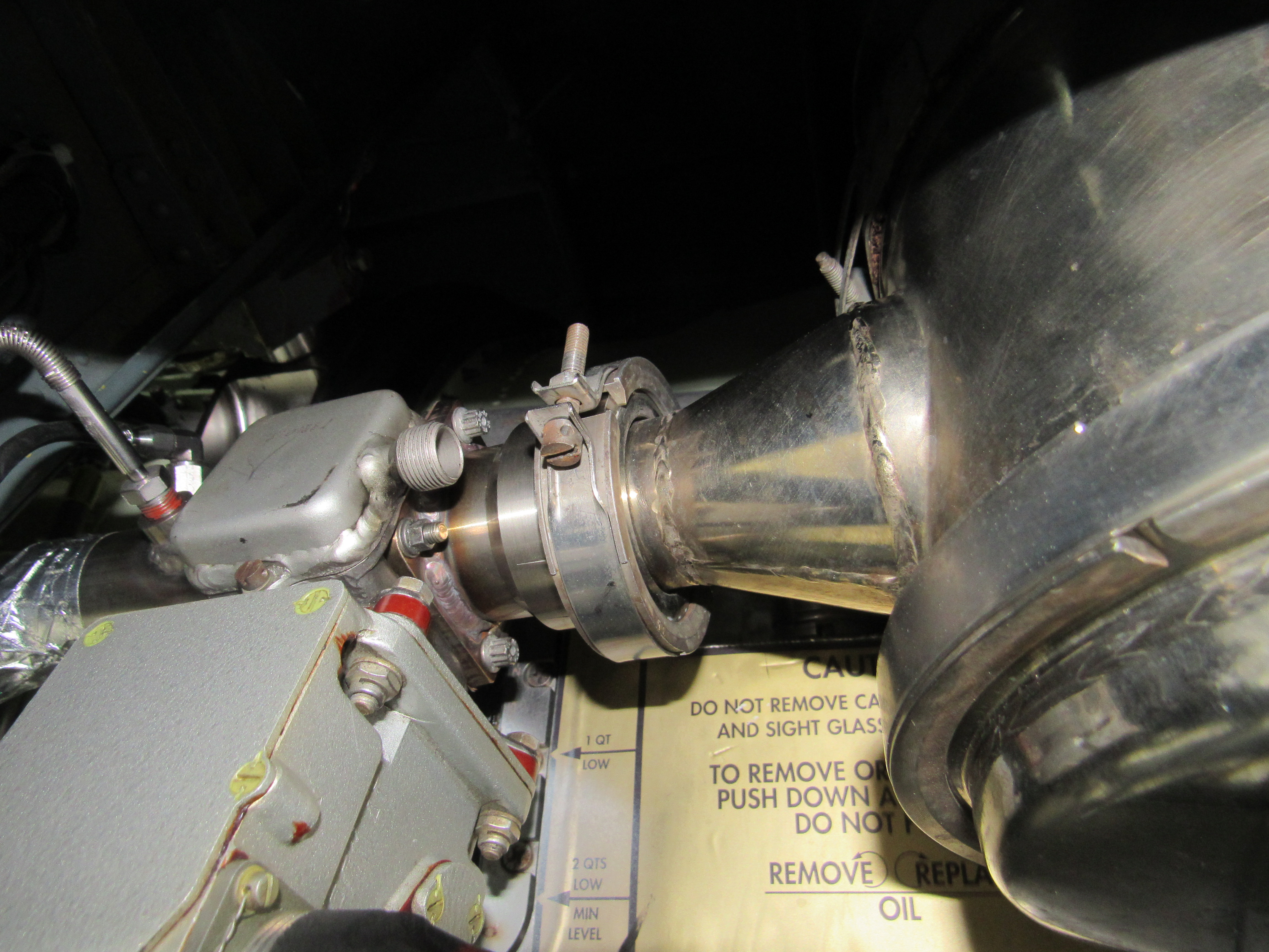
the original AI-25 bleed air shut off valves (part number LUN 567 7.22-8) which is
mounted to the original L39 air cleaner by an adapter supplied with the
installation kit. ****Note: The original L39 air cleaner bracket (the one
that touches the air cleaner) must be de-riveted and moved OUTBOARD by one rivet
hole. This is necessary to provide clearance between the air cleaner and
the TFE731-3 oil tank which sits on the front side of the motor right next to
the air cleaner.**** This completes the path from the engine to the
ACM/Pressurization system. There is a pressure sensor and a thermocouple
installed BEFORE the bleed air shut off valve (the one mounted on the air
cleaner using our adapter). A 1 1/2" tube is "Y"ed off the ACM bleed air
line going forward to supply inlet and windscreen de-ice air. This pipe
attaches to another customer supplied stock AI-25 bleed air valve mounted to the
engine/RAT bay firewall. The Engine to ACM Bleed Air Shut Off Valve and
De-Ice Shut Off Valve tubing is supplied as part of the installation kit.
The AI-25 bleed air shut off valves are provided by the customer/installer.
In addition, the installer must fabricate tubing and install the original L39
de-ice flow limiting valve (part number LUN567 7.02-8) originally mounted on the side
of the AI-25 to limit de-ice bleed air flow to the original L39 design volume.
So, to summarize, we supply the tubing and adapters in the engine bay. The
installer does the RAT bay plumbing. The customer/installer provides the
stock L39 bleed air valves and the stock de-ice flow regulating valve.
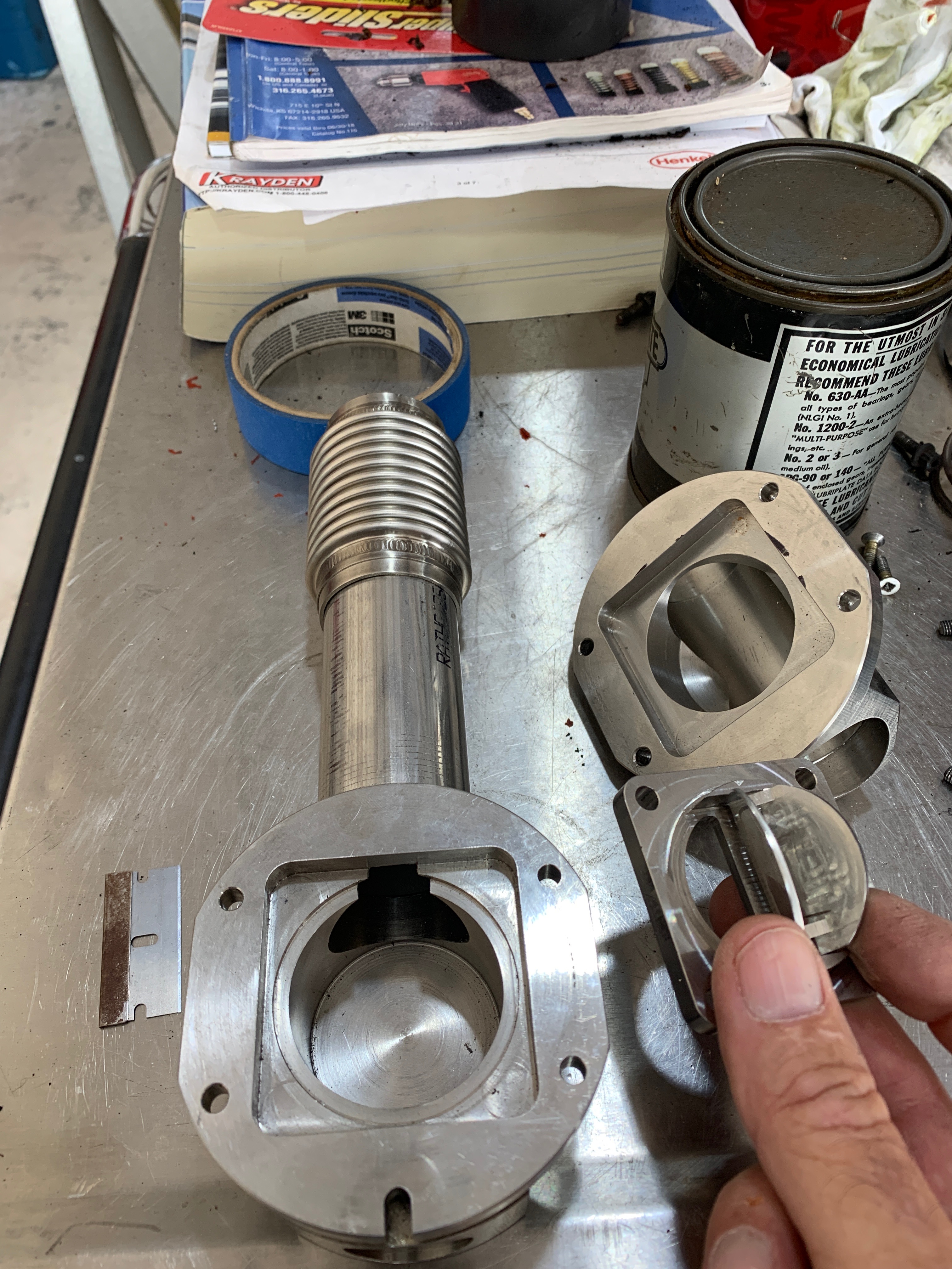
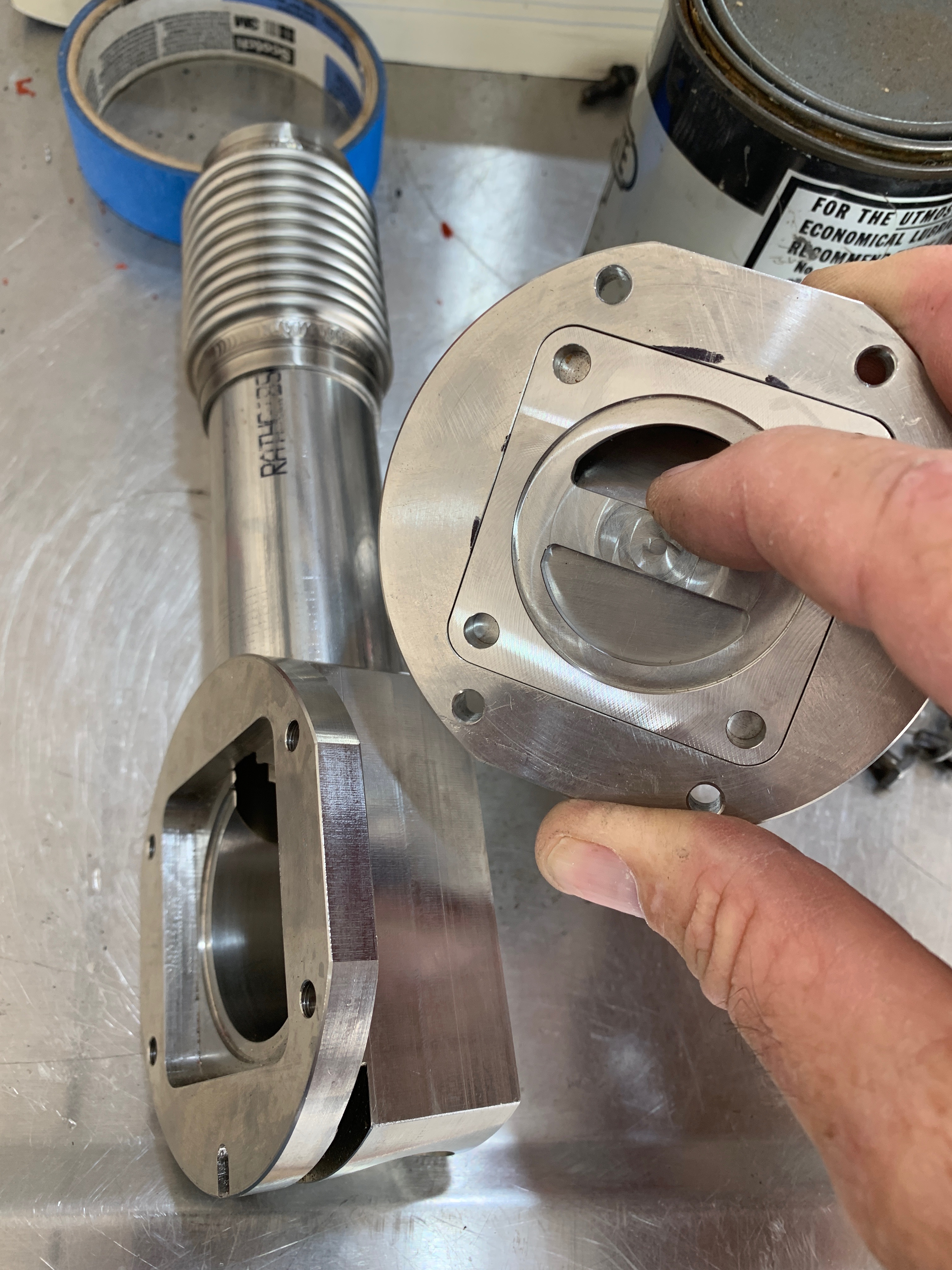
We have begun bench testing the first HP bleed air shut off valves.
Here is a quick look. I've
added a picture below of the dry graphite treated piston with PTFE seal ring.
|
|
|
|

|
|
|
|
|
|
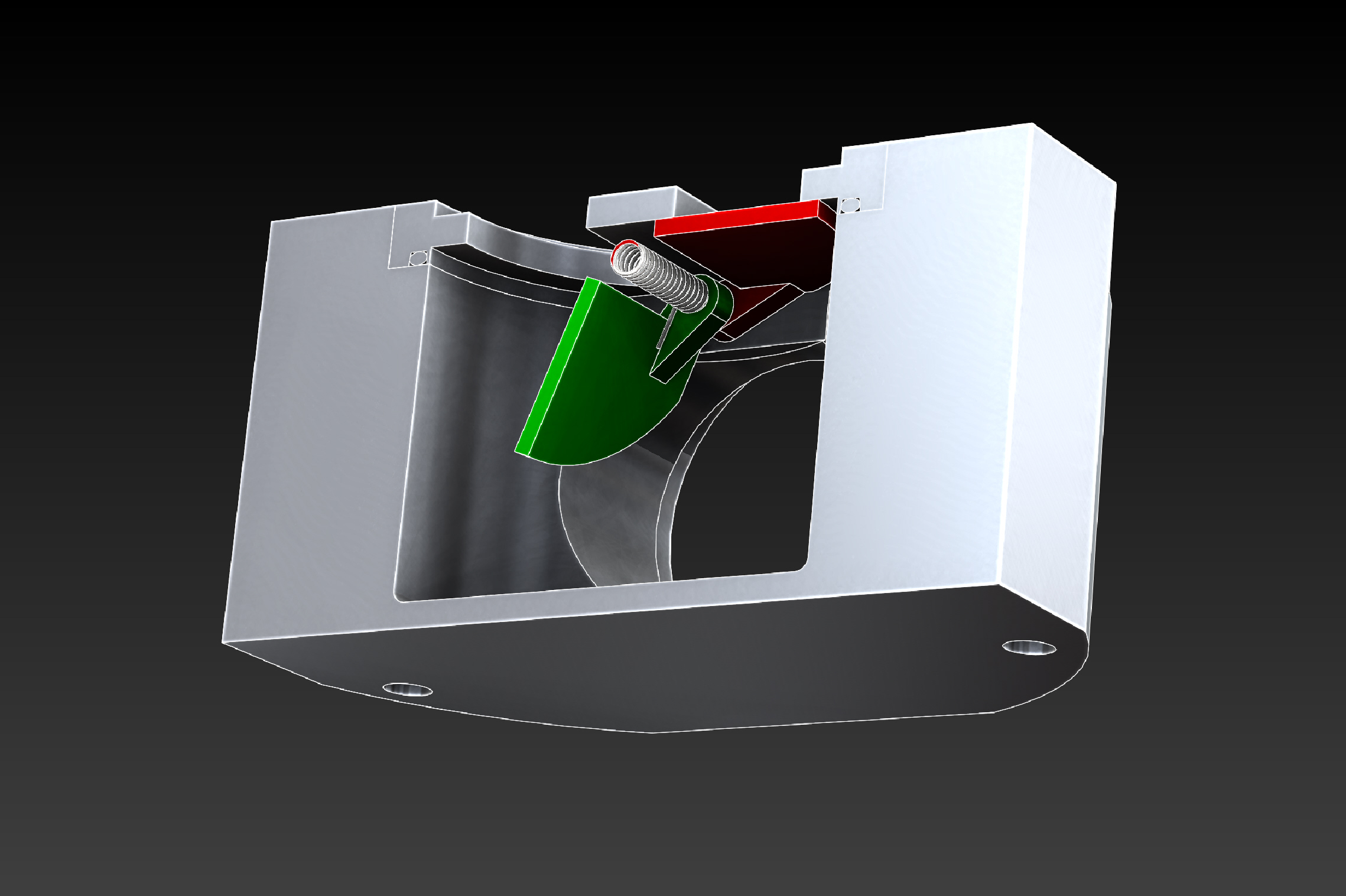
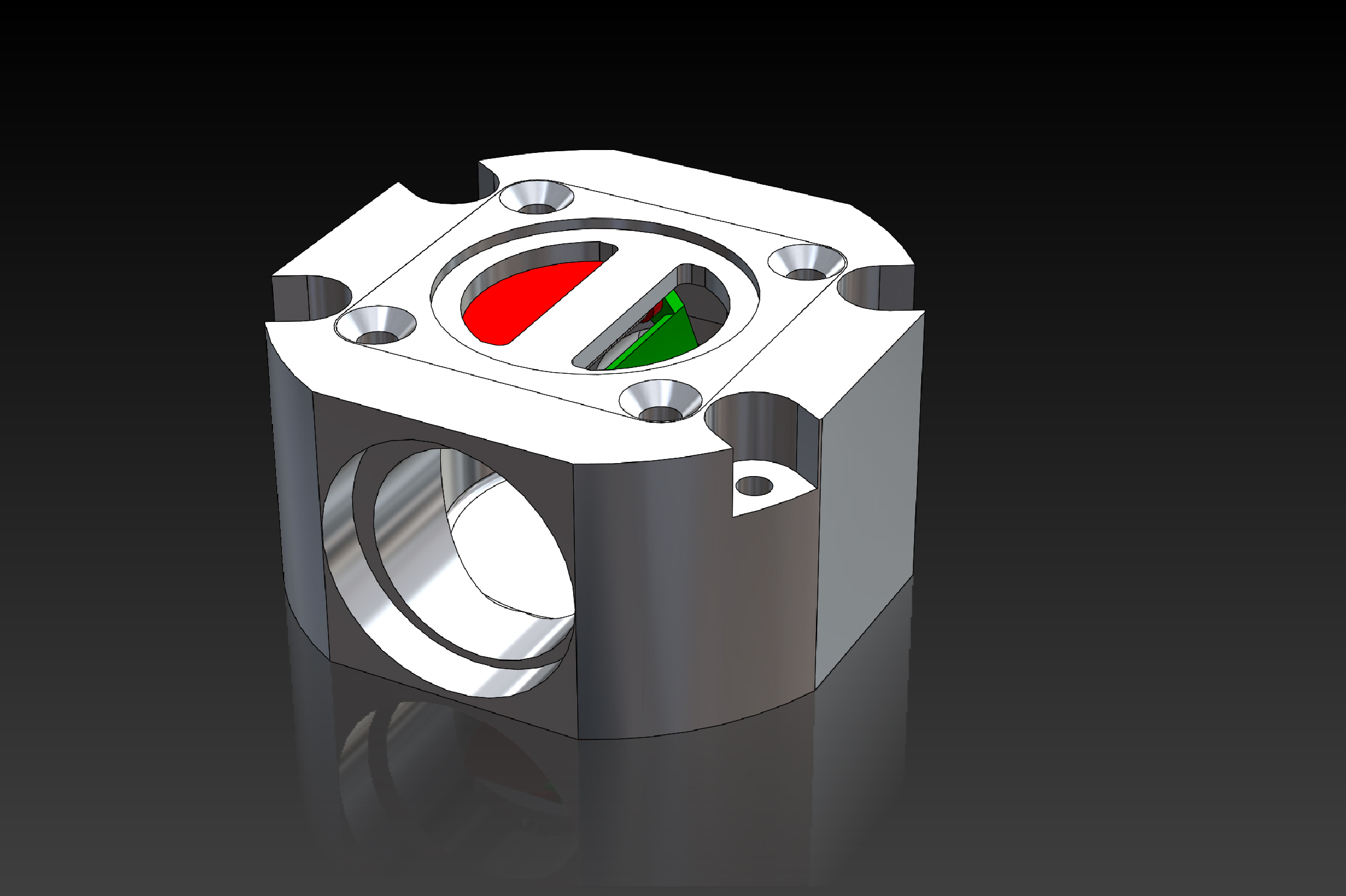
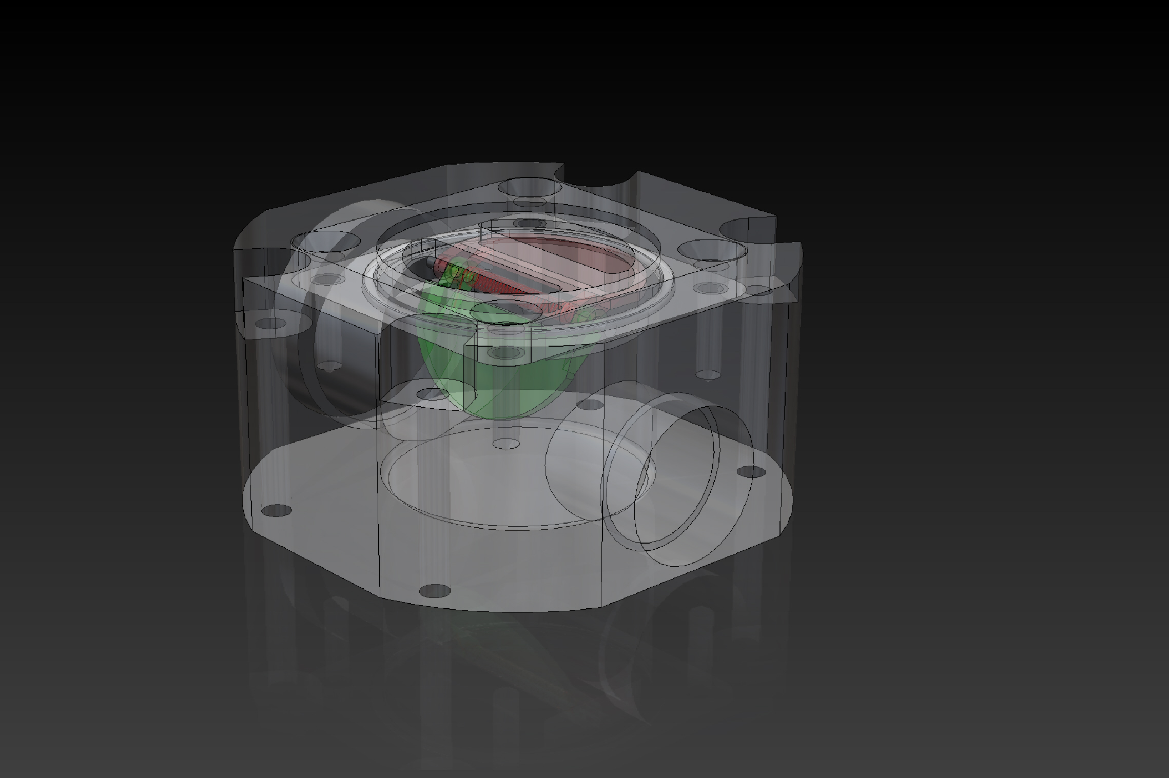
Bleed Air mixing manifold prototypes
Showing one way valve protecting the LP duct |
|
|
|
|
|
|
|
|
|
|
|
|
|
|
|
Inlet De-ice Bleed Air flow control valve (stock L39 part) |
|
|
|
|
|
|
|
|
|
|
|
|
|
ACM or Turbo Cooler flow control valve (stock L39) |
|
|
|
|
|
|
|
|
|
|
|
|
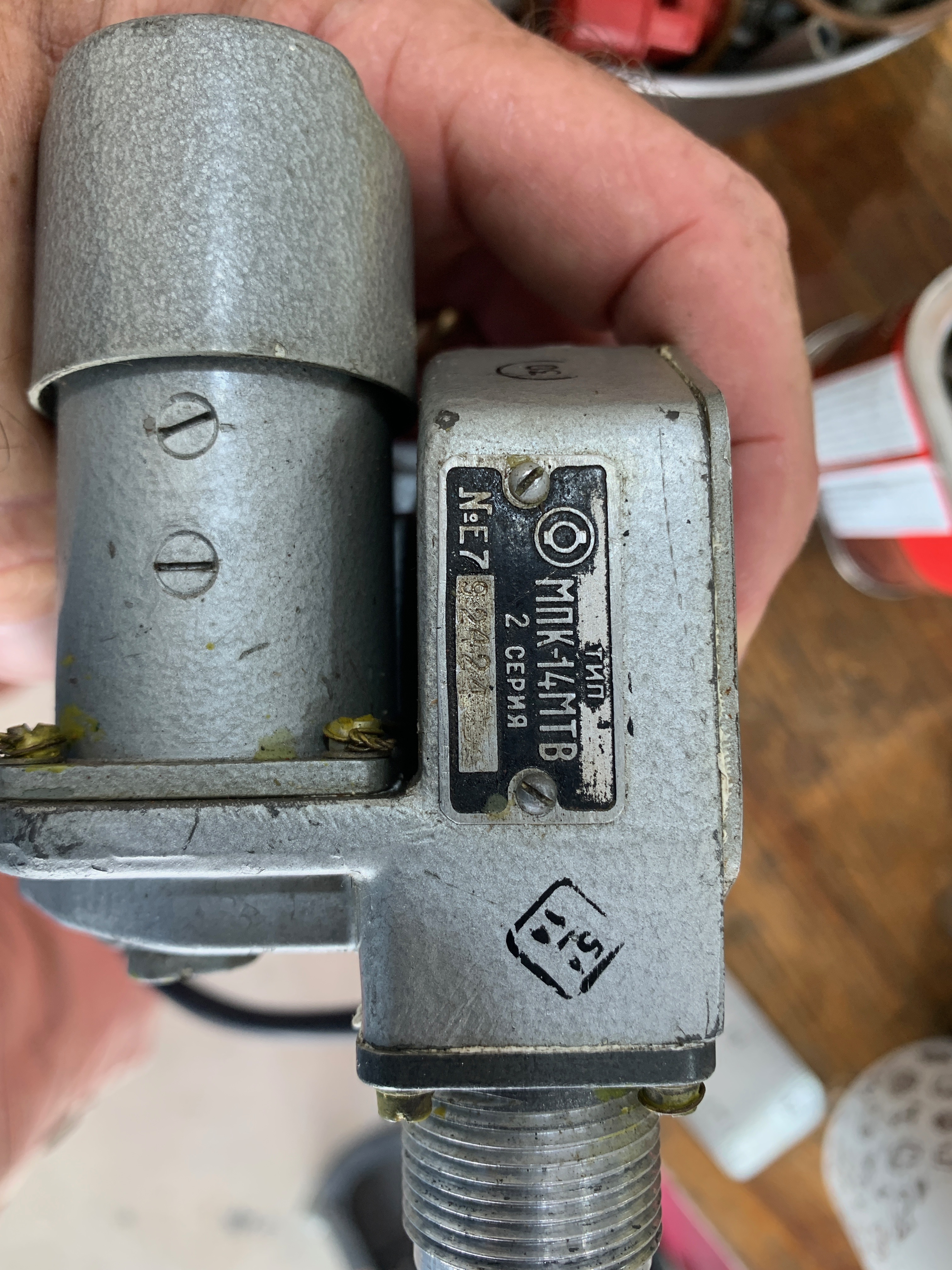
Original L39 Bleed Air Swtiching Valve |
|
|
|
|
|
|
|

|
|
|
|
|
|
Bleed Air mixing manifold prototypes |
|
|
|
|
|
|
|
|

|
|
|
|
|
|
Note the adapter allowing the orignial AI-25 bleed air shut off valve to be mounted to the air cleaner. |
|
|
|
|
|
|

|
|
|
|
HP shut off valve coated piston with PTFE seal ring |
|
|
|
|
|
|
|
|